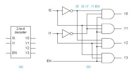
Logic Diagram Of 2 To 4 Decoder
Logic demultiplexer digital decoder implementation flop Decoder logic diagram and truth table / ks 0048 logic diagram of 3 to 8 Decoder, 3 to 8 decoder block diagram, truth table, and logic diagram
VLSI Design: Unit-V: Combinational Logic Design - DECODERS
Decoder circuit diagram gate input inputs label consider following output given each Decoder logic using tables schemas Decoder 3x8 multiplexer binary adder demultiplexer circuits inputs outputs nand generate segment integer display designing
Decoder decodificador rangkaian equations instrumentation nutshell circuitos digitales bcd ingressi combinational integrato uscite
Decoder logic diagram and truth table / ks 0048 logic diagram of 3 to 8Logic circuit diagram of 1 to 8 : logic circuit diagram of 1 to 8 Consider the following decoder circuit: a.label th...Decoder circuit ualberta webdocs courses amaral webslides cs ca ram logic diagram img027 gif constract help circuits.
2-to-4-decoder logic diagramDecoder 16 bit diagram logic line rangkaian skema elektronika koleksi artikel Vlsi design: unit-v: combinational logic designDigital logic.
Decoder 4 bit to 16 line
Nand decoder only logic circuits implementation enable input ppt powerpoint presentationDecoder binary logic digital output table truth geeksforgeeks ab Instrumentation in a nutshell: decoderLogic decoder vlsi diagram inputs figure truth table.
Encoder logic watelectronics decoderEncoder logic diagram and truth table / logic diagram and truth table Decoder logic engineersgarage encoder gates truth.