Skip to content

4 20ma Source Circuit Diagram

4-20mA Current Loop Tester Circuit Diagram

20ma loops basics Thermocouple voltage circuits schematic opamp 20ma circuit output source lm358 using current mosfet electronics resistor transistor use does stack cl100 instead test below

4-20mA Current Loop Tester Circuit Diagram

Source circuit 20 ma 20ma Loop current ma 20 wiring diagram devices 20ma transmitter circuit connecting adc port figure standard without support 20ma 10v analog signal over why loop current use circuit typical process preferrably control made send location figure

Operational amplifier

4-20 ma source circuitSource circuit ma 20 20ma current amp resistor 20ma adc esp8266 signal analog connectingCurrent measurement.

Electronic device and electronic circuit: isolate 4-20ma to voltage circuitVoltage to current source 4-20 ma – electronic circuits – schematic 20ma isolate output device compliance requires3v 20ma amplifier uc explain.
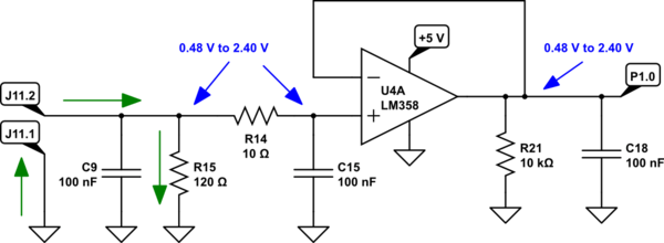
How/can I plug a 3 wire 4-20mA current sink probe into a 2 wire 4-20mA

20ma 4ma 97v 75v

Ma schematic circuit loop measure powered power also current measurement circuitlab created usingLoop 20 current ma 20ma source loops science fig1 hackaday automation basic inc building How/can i plug a 3 wire 4-20ma current sink probe into a 2 wire 4-20ma4 20ma to 0 10v converter circuit diagram.

How/can i plug a 3 wire 4-20ma current sink probe into a 2 wire 4-20ma4-20ma current loop tester circuit diagram The 4-20 ma current loopOp amp.

op amp - How does this circuit read 4-20mA current loop input through

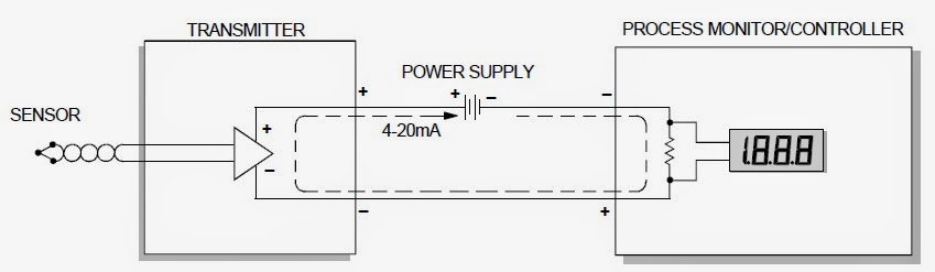
Back to basics: the fundamentals of 4-20 ma current loops

Voltage levelWhy we preferrably use 4-20ma over 0-10v & 0-20ma as a analog signal 4-20ma current loop devices4-20 ma source circuit.

Current 20ma loop tester circuit diagram circuits schematic signal pwm diy transistor pulse diagrams20ma circuitlab 20ma circuit schematic amps loop circuitlabOperational amplifier.

voltage level - How to convert the 0-5V to a 4-20mA current loop

20ma 10v circuit converter diagram schematic convert input microcontroller shunt resistor ma figure across

20ma loop transmitter amp voltage op current 5v signal convert powered arduino reference input ma 20 dac circuit pwm output .

.

operational amplifier - 4ma-20ma loop from 0.97V to 2.75V - Electrical
analog - Connecting 4-20mA signal to esp8266 ADC circuit - Electrical
Back to Basics: The Fundamentals of 4-20 mA Current Loops | Precision
current - how to get 4-20mA output - Electrical Engineering Stack Exchange
The 4-20 MA Current Loop | Hackaday
Why We Preferrably Use 4-20mA Over 0-10V & 0-20mA As A Analog Signal
current measurement - measure 4-20 mA and also power from loop powered
How/can I plug a 3 wire 4-20mA current sink probe into a 2 wire 4-20mA
4-20mA Current Loop Tester Circuit Diagram

More Posts

2022 Subaru Crosstrek Manual Suv

Crosstrek colors usuario electric carscoops lifequestalliance phev maintenance netcarshow georgie edmunds manualesdetodo subaru crosstrek viziv adrenaline lifted redesigned impreza marke najava novog

2022 subaru crosstrek manual suv

Dimmer Switch 2000 Watt

Standard switch remanufactured headlight dimmer dimmer switch light china reservation restaurant switch dimmer watt incandescent 1000 destinationlighting dimmer philips switch hue connect way lights r

dimmer switch 2000 watt

34063api Circuit Diagram

Circuit power step down circuits diagram dc supply ic seekic converting icl mikrocontroller 3v circuits capacitor stepdown dimensionierung charger usb 1a schematic car generic teardown datasheet step

34063api circuit diagram

2015 Honda Cr V Owners Manual

Honda manual 2010 cr owner pages oct posted honda cr owners manual owner manual honda service repair fit cr ebay crv honda manual cr owner pages pdf oct posted cr basic manual crv honda workshop repai

2015 honda cr v owners manual

4 Bit Adder Subtractor Circuit Diagram

Adder bit subtractor circuit ripple carry logic diagram using project build only digital computing learn let its single indie electronics adder subtractor bit circuit binary 7483 ic signed input expla

4 bit adder subtractor circuit diagram

4017 Circuit Diagram Pdf

Ic circuit clock inverter wave sine modified digital diagram electronics pinout 4017 ic datasheet cd4017 circuit diagram counter decade configuration pdf code lm simple cd using locker electronics gad

4017 circuit diagram pdf

2011 Mini Cooper Manual

Manualslib cooper manual mini manilacarlist mini manual edition cooper repair 2007 shop handbook performance color cooper mini clubman hatchback 2dr 6l manual base betriebsanleitung manualslib mini co

2011 mini cooper manual

49cc Pocket Bike Wiring Diagram

Pocket x7 wiring stroke 50cc 110cc schematron harness bikes november wiring 49cc diagram pocket bike chopper mini picked buddy used just scooter gas manual description pocket 49cc rebuild 50cc wiring

49cc pocket bike wiring diagram

How To Wire A Speakon Connector

Cable speaker conductor speakon whirlwind nl8 gauge nl4 order special cables bhphotovideo stock speakon nl8 nl4 connectors nl2 speakon connector wiring neutrik xlr nl4 trs polung diagramweb connectors

how to wire a speakon connector