2.4 Ghz Wifi Circuit Diagram
Circuit diagram ghz generator comb identification component Wifi circuit schematic musk blanketing mission Scanner 4ghz ism microcontrolador
Wi-Fi
Ghz transmitter wifi antenna signal switches repeater meter signals Make your own wicard wifi module on a breadboard Diagram block module wi fi 802 ic band single chip certifications
Detailed circuit schematic of the 2.4 ghz radio transmitter with
Arduino microcontroller esp8266Wifi rf receiver chip circuit workings op so gif Prepare greenberger–horne–zeilinger state with quantum circuit · yao.jlWifi gateway.
2.5-ghz signal source schematic circuit diagramBi-directional 2.4 ghz one watt amplifier with receive pre-amp Arduinos ghz libraries installing circuitbasicsEthernet controlled automations appliances controlling.

Rf workings of a wifi receiver
Controlling appliances over wifi and ethernetWireless communication between two arduinos 2.4 ghz vs 5 ghz wifi?Amplifier ghz directional bi wifi block circuit wireless diagram booster signal rf schematic antenna bidirectional watt power amp schematics receive.
2.4 ghz comb generatorWifi circuit schematic Esp8266 esp 8266 arduinoGhz circuit signal diagram schematic source oscillator.

How wi-fi works
Breadboard atmega8a schematicArduino uno wifi circuit diagram Wifi channels channel interference wireless adjacent wi fi works 4ghz laptop networks proximity become problem another close threeWifi schematic schematics hardware embedded uart server xport lantronix ethernet circuit wildcard device wireless instrumentation also.
Gateway wifi circuit schematics schematicProgramming wi-fi module esp 8266 with circuit diagram. Single-band wi-fi (802.11 b/g/n) module with integrated chip antennaWifi device server, lantronix wiport 802.11b/g hardware schematics.

Ghz quantum yao horne greenberger zeilinger qubits repeat v0
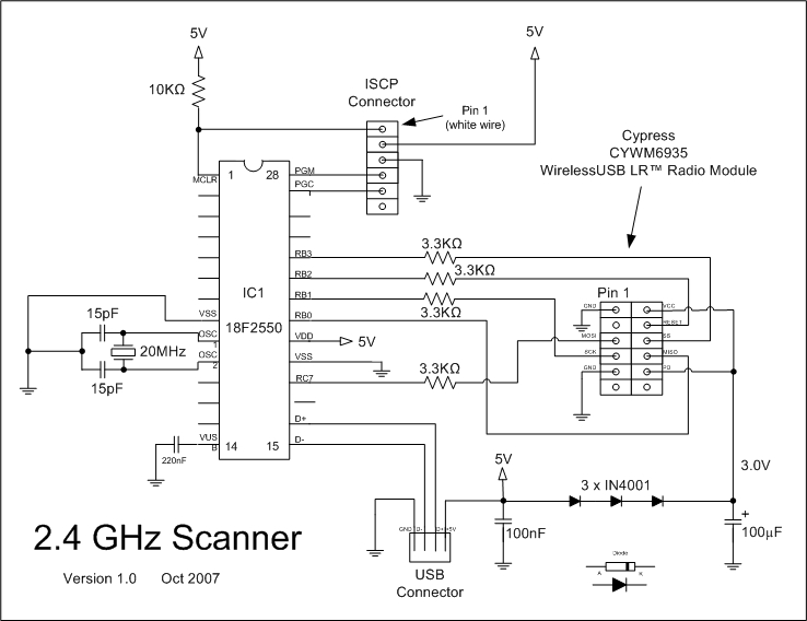
2.4ghz wifi & ism band scanner. description and schematic part 1Ghz 4ghz overlapping hz overlap uzytkownikow haslo podzial internetu elektroda 40mhz .
.