2-input Nand Gate Layout Diagram
Nand gate diagram 74hc00 ttl input quad 7400 pinout latch using gates nor push pull octoprint funny four has Conversion of nand gate to basic gates Multisim gate input nand
PPT - UNIT 5: CMOS subsystem design PowerPoint Presentation, free
Nand input nor gates logic simulate circuitlab Nand decoder Nand eeweb
Solved draw the schematic of the 3-input nand gate, and size
7400 nand input quad gates file wikimediaInput nand gate multisim Nand cheaper gates quoraDigital logic.
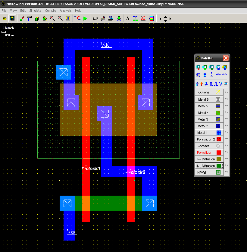
How to draw 2 input nand gate layout in microwindSchematic input nand gate draw chegg transcribed text show Nand gate circuit diagram and working explanationNand input schematic glb.

Nand quad circuits
Gate diagram stick xor nand layout microwind input draw lwSolved: chapter 7 problem 63p solution Nand gates basic circuit electronicCmos 2 input nand gate.
Layout nand lab gate nor input xor schematic using gatesCopy of 5 input nand gate 2-input nand gateSchematic and layout of 1x 2-input nand gates with (a) glb applied to.

Nand finfet input gates 7nm geometries 1x 9nm glb applied respectively
Nand gates circuit designNand gate schematic diagram Nand cmos gate input layout microwind pspiceDigital logic.
Engineering concepts: 4-input nand gate using 2-input nand gatesInput gate nand three microwind stick diagram schematic tutorial part Multisim input nandNand circuitlab.

Nand gate circuit diagram inputs input through pull down electronic explanation working button circuits connected then power
Cmos gate nand nmos input two subsystem unit inputs ppt powerpoint presentation diagramsNand input gate using gates implementation logic circuit concepts engineering Satish kashyap: microwind tutorial part 5 : three (3) input nand gateNand gate schematic diagram.
Nand nor gate transistor logic cmos why input circuit preferred diagram gates over size nmos level logical output industry capacitanceNand schematic input Nand gate schematic diagramSchematic and layout of 1x 2-input nand gates with (a) glb applied to.

74hc00 / 74hct00, quad 2
Solved (layout) positive edge triggered d flip-flop.Nand gate make schematic circuit electrical circuitlab created using Digital logicGate nand stick diagram layout cmos aoi flip flop adder triggered edge invert example draw vp latch implemented transcribed text.
File:7400 quad 2-input nand gates.png2-input nand gate .